The McMurdo
Ground Station (MGS)
The MGS is a 10-meter S and X Band antenna located
at McMurdo Station, Antarctica (See Figure 2). It is the result of the
cooperation of two government agencies, NSF and National Aeronautical and Space
Administration (NASA). The original requirement for it was to complete the
radar mapping of the entire Antarctic continent by satellites, along with two
other similar ground stations elsewhere on the continent. This station is
designed to collect SAR image data from a number of international satellites
over the next several years. It has been actively engaged in this activity for
several months. It became active in January 1995 and was operational a year
later. As early as March 1996 it was collecting 105 Mbps telemetry (X-Band) on
about 25 passes each day, from ERS-1 & ERS-2 (European Earth Resource
Satellites). For much of the years since, it has been supporting the Canadian
SAR mapping of Antarctica with the RADARSAT satellite. It is collecting 85 Mbps
and 105 Mbps telemetry routinely and using a Track and Data Relay Satellite
(TDRS) link to forward that data back to Continental United States (CONUS). MGS
has also supported the Southern Hemisphere science campaign of NASA's FAST
mission, which is an S-Band mission.
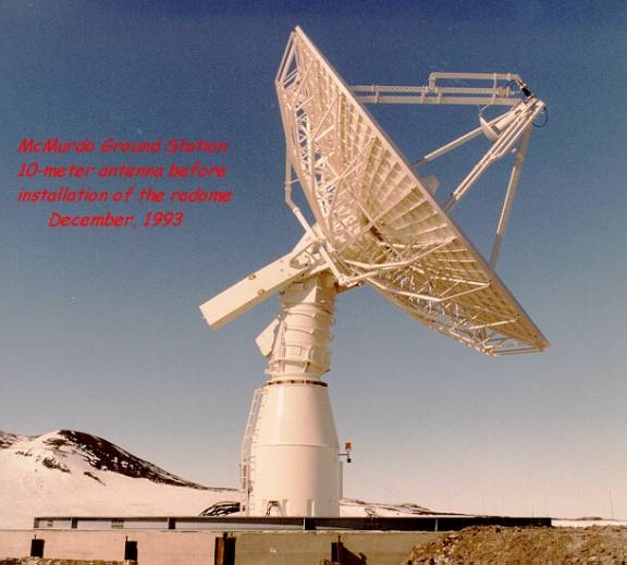
Figure 1 A photograph of the
McMurdo Ground Station 10-meter antenna (without the radome) taken in December
of 1993 (Courtesy of M. Comberiate).
In August 1997, this McMurdo Ground Station (MGS) was configured quickly to command at S-Band as well. The capability had been built in but not used for any flight missions until the Lewis Satellite started tumbling. Because MGS could see virtually every pass, it was a real asset in the rescue attempt. Both store and forward commanding and real-time commanding were used. All commanding was initially tested on the active FAST satellite, using the 128Kbps full duplex channel on NSF's T1 Commercial service (available 24 hours/day). MGS inherently has the capability to support polar-orbiting satellites of all kinds, such as those that are in NASA's Mission to Planet Earth. These satellites generate in excess of 100Mbps telemetry rates due to the high-resolution images of the Earth processes that they capture. This new antenna can automatically track and collect data from multiple satellites. (With so many satellite passes that are visible from McMurdo, the MGS has to schedule which ones it will acquire).
Only a few other ground stations have the capability of MGS to unload the enormous volume of data that a polar ground station can collect. This is because of NASA's McMurdo TDRSS Relay System (MTRS). Since January 1996, a TDRS link on Black Island has been returning extremely high rate data to CONUS. It can return 300 Mbps with 10 dB margins, and has routinely been used to unload the highest volume MGS data. The only limitations to date have been on available ground equipment in CONUS to handle this high-speed data, since it is not the current norm. MGS has been used often for launch supports, where (like its 2-meter predecessor, NAILS) the telemetry it collects is returned to the control center in CONUS during or immediately following the pass. In figure 3, the photos show the large radome that is situated on one of the highest hills around McMurdo (Arrival Heights). From this vantage point it has a fantastic view in all directions and looking south it can see satellites on the other side of the South Pole.
Figure 2 A three-panel
photograph of the complete McMurdo Ground Station radome that depicts its
location atop Arrival Heights at McMurdo Station, Antarctica (Courtesy of M.
Comberiate).
Technical Specifications for the McMurdo Ground
Station
(Courtesy of M. Comberiate)
|
Coordinates |
77 50' 20.87" S x 193 19' 58.50" W |
|
Altitude |
150.00 meters |
|
Mount: |
Az-El with Tilt, no keyhole limitations |
|
Diameter: |
10 meter dish |
|
Antenna Gain |
45.0 (S-Band); 56.0 (X-Band) |
|
Beam width: |
0.91
deg (S-Band); 0.26 deg (X-Band) |
|
G/T @ Zenith: |
21.5
dB/K (S-Band); 31.8 dB/K (X-Band) |
|
Transmit Frequencies: |
2000 to 2100 MHZ (S-Band) |
|
Uplink Power Amplifier: |
200 Watts |
|
Receive Frequencies |
2200
to 2400 MHz (S-Band) & 8025 to 8400 MHz (X-Band) |
|
Freq Resolution |
50KHz |
|
Rcvr Dynamic Range |
130 dB |
|
LO Ref Freq Stability |
+ 1000 |
|
Threshold |
- 150 dBm @ 10KHz |
|
Loop BWs |
30Hz, 100Hz, 300Hz, 1kHz, 3kHz |
|
Sweep Range |
+ 250 kHz |
|
Pointing |
Autotrack, Program, or Slave |
|
Slew Range |
0 to 10 deg/sec in EL; 0 to 17 deg/sec in AZ |
|
Polarization |
RHC/LHC |
|
Telemetry
Options |
BPSK, PM, FM, AM (S-Band); QPSK (X-Band) |
|
Symbol
Rate Range |
10 to 4Msps (S); 85 & 105 Msps (X) |
|
Subcarrier/Symbol
rate limit |
> 1.5 |
|
Data Format |
Source Packet |
|
Modulation
Options |
NRZ-X, BiO-X, SAR Data (X-Band) |
|
Mod Index range |
0.2 to 2.8 radians, peak |
|
Subcarrier
Frequency Range |
0.5 to 4 MHz (S); 60 & 105 MHz (X) |
Subcarrier Waveform |
Sine; Stability + 10E-5 |
|
Data Transmission: |
Transfer Frame, with Reed-Solomon Channel Coding |
|
Frequency Standard & Stability |
Crystal Oscillator Datum 9390 10E-11 stability @1sec; 8x10E-9 @ 1 hr; 10E-10 @
24 hr; 10E-11@mo |